How to read this page
Everything below is design intent. No part of it has been built or measured. Figures are either calculated requirements, design targets, or stated assumptions — and each one is labelled as such. Nothing here is a test result.
1. The pressure budget
The starting point is not a new energy source. It is an existing one that is currently spent on nothing.
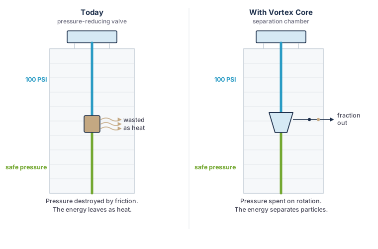
A twenty-storey building pumps water to a roof tank. By the time that water reaches the lower floors, the column above it has produced something in the region of 80–100 PSI at the base of the riser. Domestic fixtures and fittings are rated for a fraction of that, so a pressure-reducing valve dissipates the surplus as friction and heat. It is deliberate, universal, and it wastes a genuinely useful quantity of energy.
Vortex Core replaces that valve with a tangential inlet. The water is not allowed to lose its pressure quietly — it is injected tangentially into a conical chamber at 2–5 m/s and forced into a tight spiral. Head pressure becomes rotational velocity. The device still delivers the pressure reduction the building required; it simply takes payment for it in useful work.
Design target: 2,500–3,000 G sustained at roughly 80 PSI inlet and design flow. Whether that is reachable in a compact device is one of the questions we cannot yet answer.
2. Three stages, each using a different property
A single separator cannot resolve particles that behave in opposite ways. The concept therefore uses three stages in series, each targeting a different physical difference.
Stage 1 — heavy fraction
Water enters tangentially and forms a tight vortex. Particles denser than water — PET and PVC at 1.3–1.5 g/cm³, along with sand and sediment — are slung to the outer wall and fall through an apex valve. Design target: removal of particles above 20 µm.
Stage 2 — light fraction
The centre of a vortex is a low-pressure eye. Polymers lighter than water — polyethylene and polypropylene at 0.85–0.95 g/cm³ — migrate inward rather than outward, and can be skimmed from that core instead of being left in the product water. This is the stage with the hardest physics in it.
Stage 3 — polishing
A UV-C chamber for biological safety, and optionally a carbon block for taste and odour. This stage is conventional water treatment, included because a separator is not a disinfectant and should not be presented as one.
3. What the device would look like
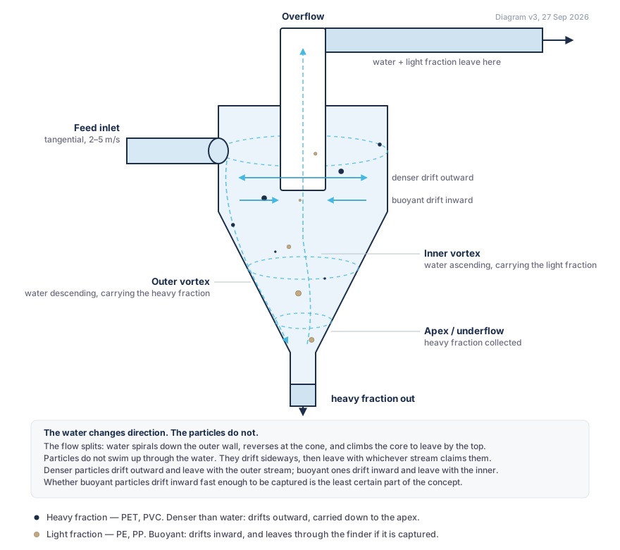
A cross-section of the intended arrangement. Two things in it are easy to misread: the water changes direction, and the particles do not.
Why the particles are not swimming upstream
A drawing like this invites an obvious objection: water only travels down, so how can anything travel up it? The answer is that the water itself changes direction, and most of it leaves by the top. In a hydrocyclone the flow splits into two co-axial vortices — an outer one descending the wall, and an inner one climbing the core to the overflow. That is what the vortex finder is for, and it is why the device has two outlets.
The particles are carried by that water. They do not push upward against the current. The separation actually happens sideways: in the centrifugal field, material denser than water drifts outward while material less dense drifts inward, and each is then transported by whichever vortex takes it. The two drift arrows on the diagram are the whole mechanism; the vertical movement is only the transport afterwards.
The flow split does have a consequence for how the thing would be plumbed in, and it is worth stating because it is easy to miss: the product water leaves by the top outlet, so it has to be piped back down the riser to reach the floors below. That is an additional run of pipe, and it is the reason this is not a like-for-like swap for a pressure-reducing valve.
The weak point, stated plainly
Radial drift is well proven for dense solids. It is far less proven for buoyant particles, which is the case this concept depends on. Three things make buoyant capture harder: the density difference driving the drift is small; the central core of a hydrocyclone is typically an air core rather than water, so a floating particle may sit at a free surface rather than being skimmed; and the argument depends on the inward drift being fast enough to reach the core before the water carrying it leaves the bottom.
That is why feasibility treats light-fraction capture as an open question rather than a design feature, and why the next step is a numerical model rather than a nicer drawing. It is also entirely possible that a hydrocyclone is simply the wrong device for buoyant material, and that this needs a different separation principle altogether. A model should be able to tell us that — and if it does, that is a useful answer, not a failure.
4. Where each stream goes
The chamber produces two streams rather than one clean and one dirty. Where they go is a separate question from how the separation works, so it is drawn separately.
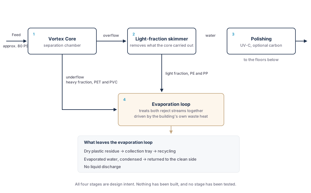
The concept routes both reject streams — the underflow, estimated at 5–10% of total flow, plus the smaller skimmed light fraction — through a heat exchanger fed by the building’s own waste heat: chiller returns, server room exhaust, or solar gain. The water evaporates; the plastic does not. What is condensed back is clean water, and what remains is a dry residue that can be collected in a tray and sent for recycling rather than discharged as liquid waste.
Two honest caveats. First, the energy balance of this loop has not been calculated in detail; “waste” heat is not the same as available heat, and it may not be available when the loop needs to run. Second, a system that removes particles above roughly 15 µm is a pre-treatment step, not a complete potable water treatment train, and should not be described as one.
5. The physics question, stated plainly
This is the part that decides whether the concept is viable. It is also the part most easily glossed over, so here it is in full.
The rate at which a suspended particle migrates under centrifugal force follows a form of Stokes’ law:
where d is particle diameter, ρp and ρf are the densities of particle and fluid, ac is centrifugal acceleration, and η is viscosity. Two things follow immediately: separation gets harder as the square of particle size, and harder as the density difference shrinks.
| Particle size | Polymer | Behaviour | G-force required | Within our 2,500–3,000 G design point? |
|---|---|---|---|---|
| 50 µm | PET | Denser than water | 19 G | Comfortably |
| 50 µm | Polyethylene | Buoyant | 147 G | Comfortably |
| 5 µm | PET | Denser than water | 1,931 G | Yes |
| 5 µm | Polyethylene | Buoyant | 14,679 G | No — order of magnitude short |
The gap, named
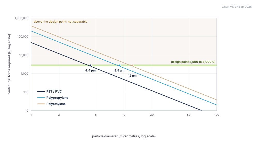
At 5 µm, buoyant polymers need three to six times our design point — 8,000 G for polypropylene and 15,200 G for polyethylene. Kinetic energy scales with the square of velocity, so reaching those numbers by spinning faster is not an adjustment to the same machine; it is a different machine, with different pressures and different wear.
There is a second risk that matters as much as the first: a single chamber tuned to eject heavy PET can concentrate light polypropylene in the stream it declares clean. Any design must demonstrate that it does not simply move a problem from one species to another. How we plan to test both →
6. Where it could go
The intended deployment is one device per riser, at or near where the pressure-reducing valve already sits.
Retrofit
In an existing building, the device occupies a plant-room position adjacent to existing pressure control. No new energy supply is required, which is the single biggest practical advantage of the concept.
New build
Designed in from the start, the pressure budget, riser layout and waste-heat access can all be arranged to suit. This is where the concept is most likely to work well.
A visible installation
The chamber is a glass-and-steel object with water visible inside it. That is an opportunity but also a commitment: a public-facing installation has to work, and has to be honest about what it is doing.
Next: what we can actually prove
The concept is not the hard part. Knowing whether it is real is. Here is what exists, what does not, and the order we intend to work in.