
Where this actually stands
Vortex Core has not been built, tested or certified. There is no prototype, no test rig, no simulation output and no patent application. What exists is a detailed engineering concept, the physics that has to hold for it to work, and an honest list of the questions we cannot yet answer.
We are publishing it at this stage on purpose. If the concept is sound, the fastest way to find out is in simulation — and that work is easier to do with others than alone. See the open questions →
The problem worth attacking
Two long-standing problems in the same place: what is in the water, and what it costs to work around it.
Microplastics are in the water supply
Microplastics have been detected in drinking water sources and in bottled water worldwide. The World Health Organization reviewed the evidence in 2019 and judged the health risk at current exposure levels to be low, while identifying substantial gaps in the data. The concern is real; the certainty is not yet there.
Tall buildings waste their own pressure
Water pumped to a roof tank arrives at the base of the riser at roughly 80–100 PSI — far above what fixtures allow. Pressure-reducing valves shed that surplus as friction and heat. It is a genuine energy stream, discarded by design.
Bottled water is a recurring liability
Buildings that supply bottled water to guests, staff or residents carry a permanent cost and a permanent plastic waste stream. Removing the reason to buy it is more durable than paying to manage it.
The idea in three moves
Each stage exists to exploit a physical difference that already exists in the water.
1. Spend the pressure, don’t lose it
Replace the pressure-reducing valve with a tangential inlet. Water enters at 2–5 m/s and is forced into a tight spiral, converting head pressure into rotational energy — and delivering the pressure reduction the building needed anyway.
2. Let density do the sorting
Heavy plastics — PET and PVC at 1.3–1.5 g/cm³ — are thrown outward and fall to a collection point. Light polymers — PE and PP at 0.85–0.95 g/cm³ — are drawn into the low-pressure core and skimmed off. Water sits in the middle.
3. Evaporate what is left
The reject stream is a small fraction of total flow. Routing it past the building’s own waste heat — chiller returns, server rooms, solar gain — drives off the water and leaves dry plastic for recycling, rather than a liquid waste discharge.
Update: catching the dense fraction on the way past
A second arrangement of the same chamber, added 28 September 2026.
In the arrangement used above, heavy plastics fall the full length of the cone and leave at the apex. A variation diverts them earlier: a lip on the wall turns the outer stream — the layer the dense particles have been thrown into — into a scoop and out to a trough on each side. The bottom outlet then carries mostly water instead of a loaded slurry.
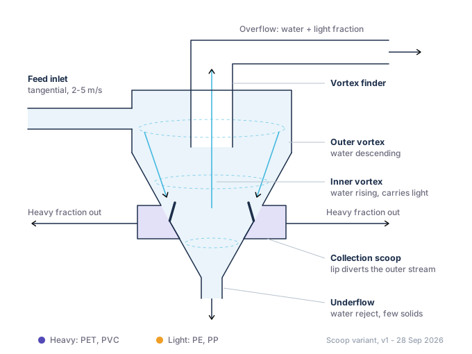
Neither arrangement is known to be the better one. A scoop captures the dense fraction while it is still concentrated against the wall, but it puts a lip and a trough inside the vessel, where they can wear or block. The plain apex underflow adds no internal geometry at all, but it carries more water out with the plastic. That trade-off is one of the open questions the simulation has to settle.
The honest hard part
Centrifugal separation works. The open question is whether it works on the particle sizes that matter, at the pressures a real building provides.
The force required rises steeply as particles get smaller. At 50 µm, separating polyethylene needs around 147 G; at 5 µm the same calculation gives roughly 14,679 G. Our design point is 2,500–3,000 G, which comfortably covers larger particles and smaller, denser ones — but not the smallest buoyant plastics.
There is a second, subtler risk: a separator tuned to eject heavy PET can concentrate light polypropylene in the stream it declares clean. A device that halves a problem and hides the other half would be worse than useless.
Both questions are answerable by modelling before anything is built. That is the work we want to do next, and the reason this page exists. What we plan to test, and how →
Interested in this?
We are looking for people with an interest in the digital simulation, in the patent position, or in the engineering itself. Genuine enquiries only — but any serious one will get a reply.